BWD11 315.9 mm
DBD11 315.9 mm
LSD11 203 mm
356.8 mm
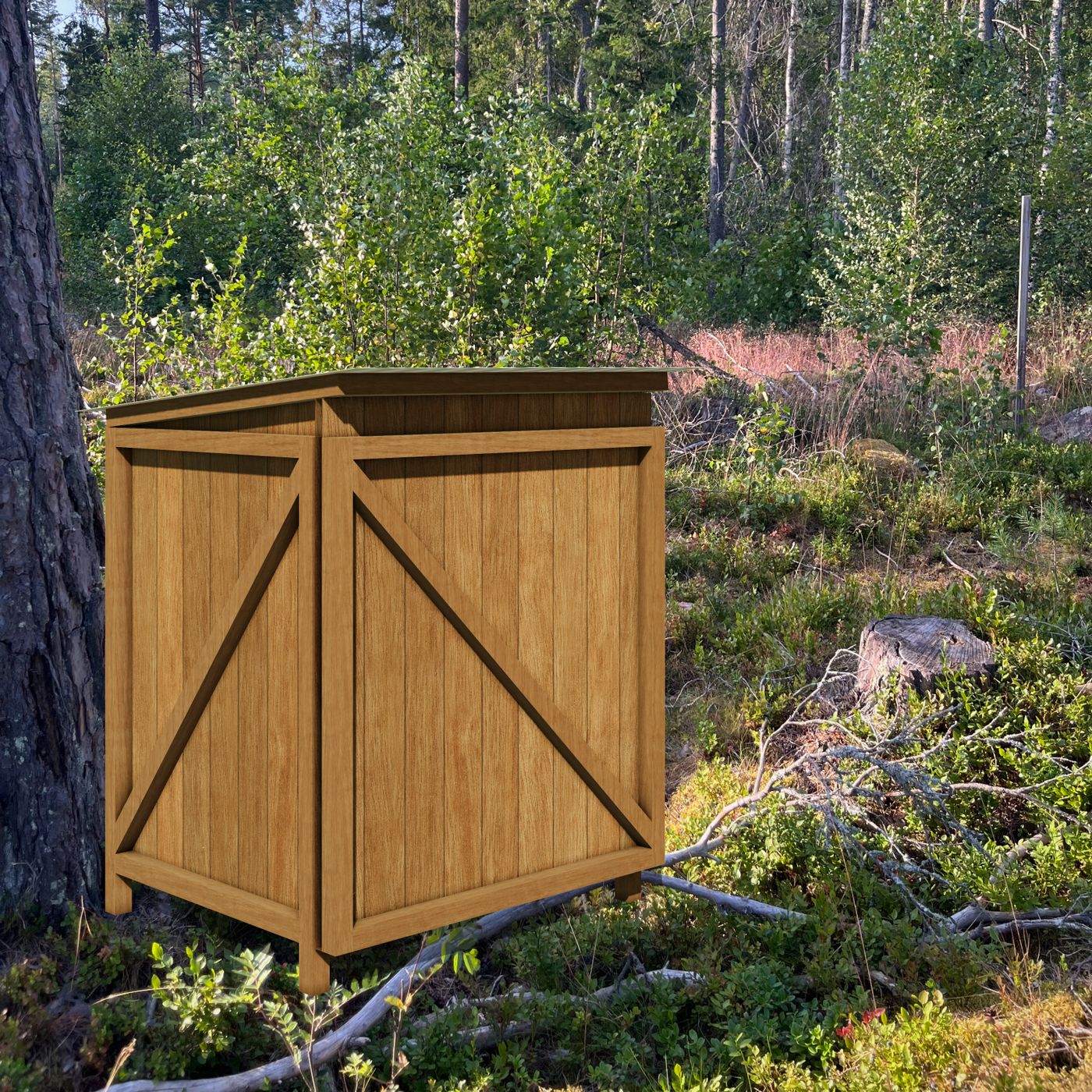
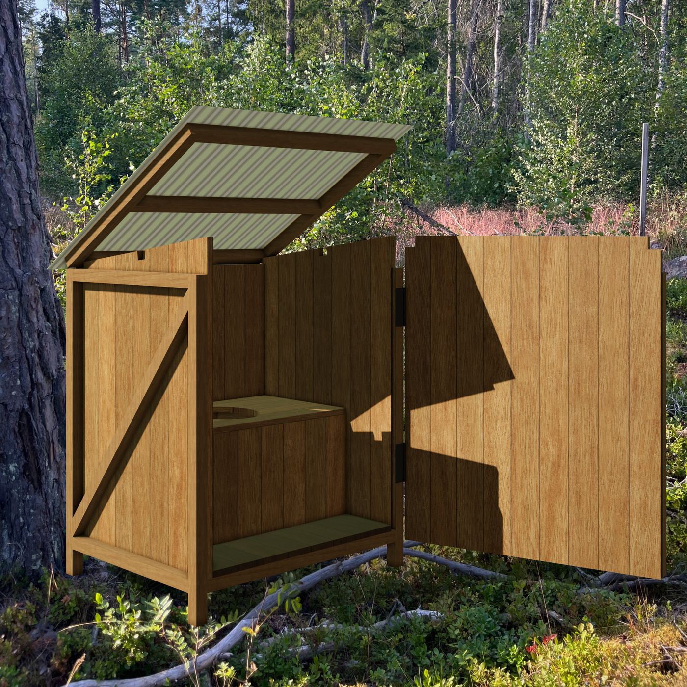
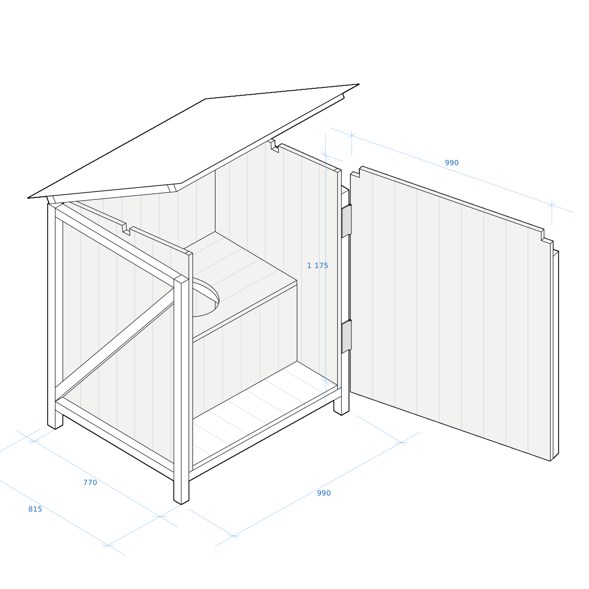
An experiment in re-drawing a technical drawing as an editable parametric CAD model with Claude and Codex.
Loading the model…
Frame timber, 45 × 45 × 4 200 mm. Quantity: 9 lengths.
The 9 beam stock lengths below are named B01 to B09. Each cut diagram shows the marked beam pieces cut from that length.
Cut every piece at one stop setting before you change the stop. A batch that reaches the end of a stock length continues on the next length.
These sheets are exact only for this material size. One 2.8 mm kerf is used for every piece.
If your material ends are rough, shave a small amount off from each piece first.
Råspont (matchboard/V-groove cladding), 120 × 23 × 4 500 mm. Quantity: 12 lengths.
The 12 cladding stock lengths below are named P01 to P12. Each cut diagram shows the marked boards cut from that length.
The first 8 stock lengths release all twenty-three 1 175 blanks. Label the P01 to P03 remainders. Keep them for the final 397 pass. Fourteen side boards come next, then nine door boards, at one stop setting.
These sheets are exact only for this material size. One 2.8 mm kerf is used for every piece.
If your material ends are rough, shave a small amount off from each piece first.
Gaps between boards change the joined width. Fix each board to its unit frame before you mark any final edge. Use the frame edge to set the circular-saw guide. Cut only after the boards are fixed. Sheet A-400 shows each estimated overhang and cut line.
Each unit opens with its general arrangement, dimensioned and coded off the model, then builds through its own numbered steps. A step draws one operation: work already done ghosts back, work this step touches goes solid, and the band under the drawing names the operation before the caption is read.
Black screw paths are measured 120 mm screws: each starts on the source beam and finishes in the centre of the receiving section. Diagonal paths follow the diagonal beam from its mitred end.
Use these fasteners for the timber assembly.
| Use | Fastener |
|---|---|
| Frame beams and braces | 6 × 120 mm sunk wood screws |
| Beam-to-beam support joints, for example floor supports | 6 × 90 mm sunk wood screws |
| Råspont (matchboard/V-groove cladding) to beams | 2.8 × 60 mm nails or 6 × 60 mm sunk wood screws |