FIELD NOTES
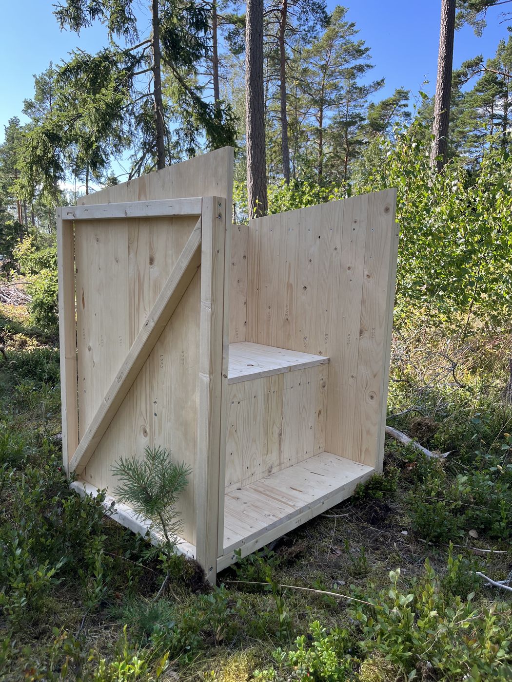
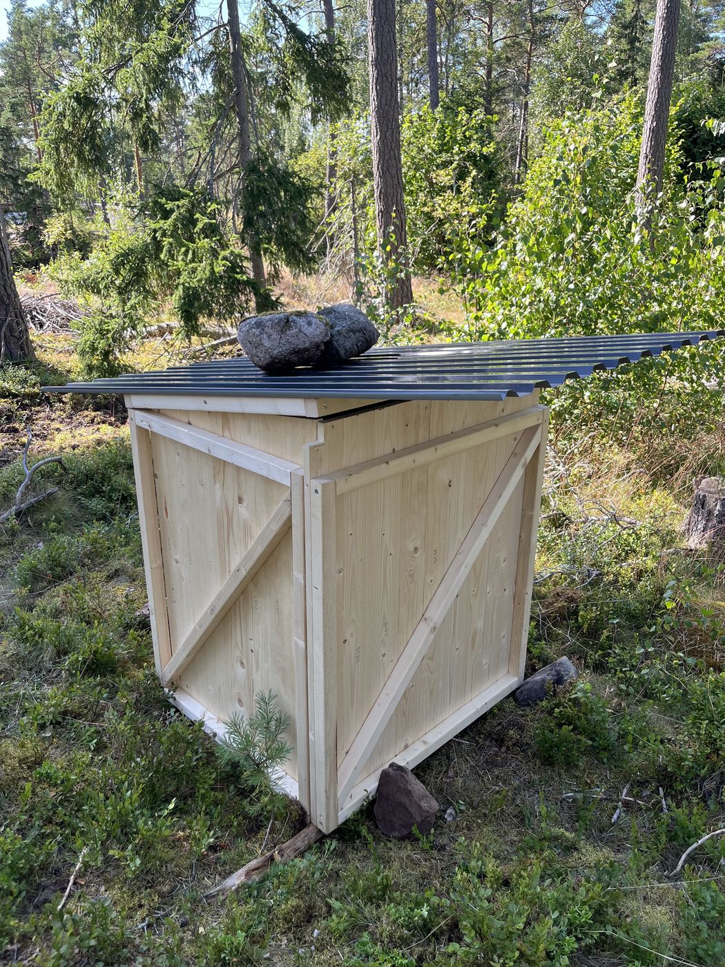
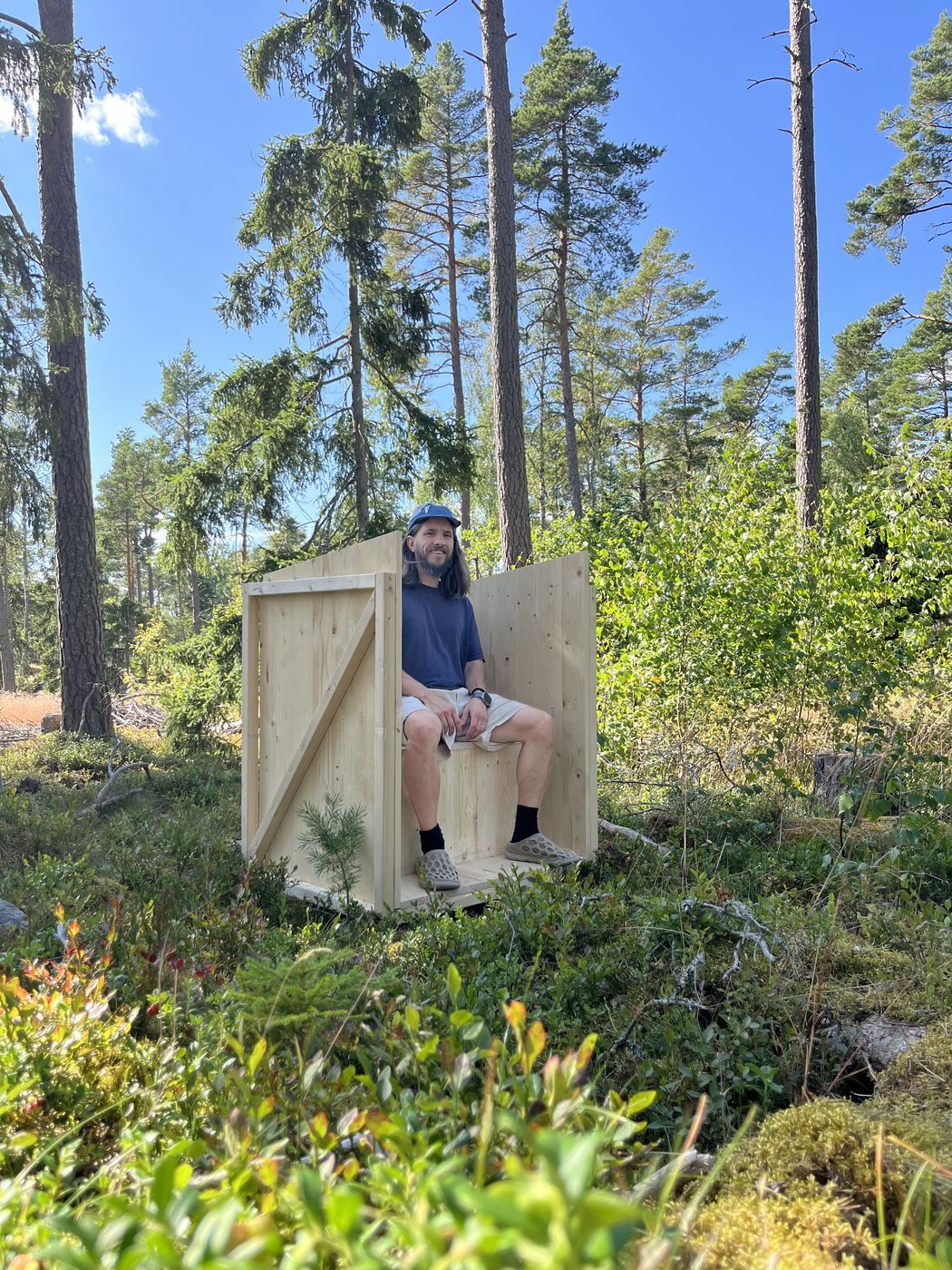
Can AI build a toilet yet?
Field notes 01
How it's going
Model 0.1.8 · the unit sheets carry their drawings and nothing else.
Model changelog
- The unit sheets drop their Hold boxes, so a unit's general arrangement runs straight into its first numbered step.
- Both finishes are projected in parallel at the unit sheets' elevation, timber is white throughout, the linework is drawn at its stated weights and cut around a heavier silhouette, and the ground, side wall, and door carry dimensions measured off the model.
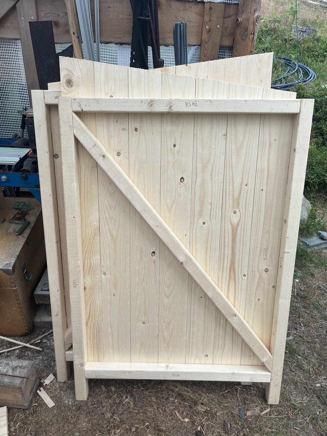
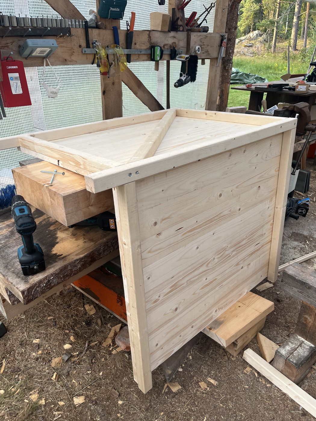
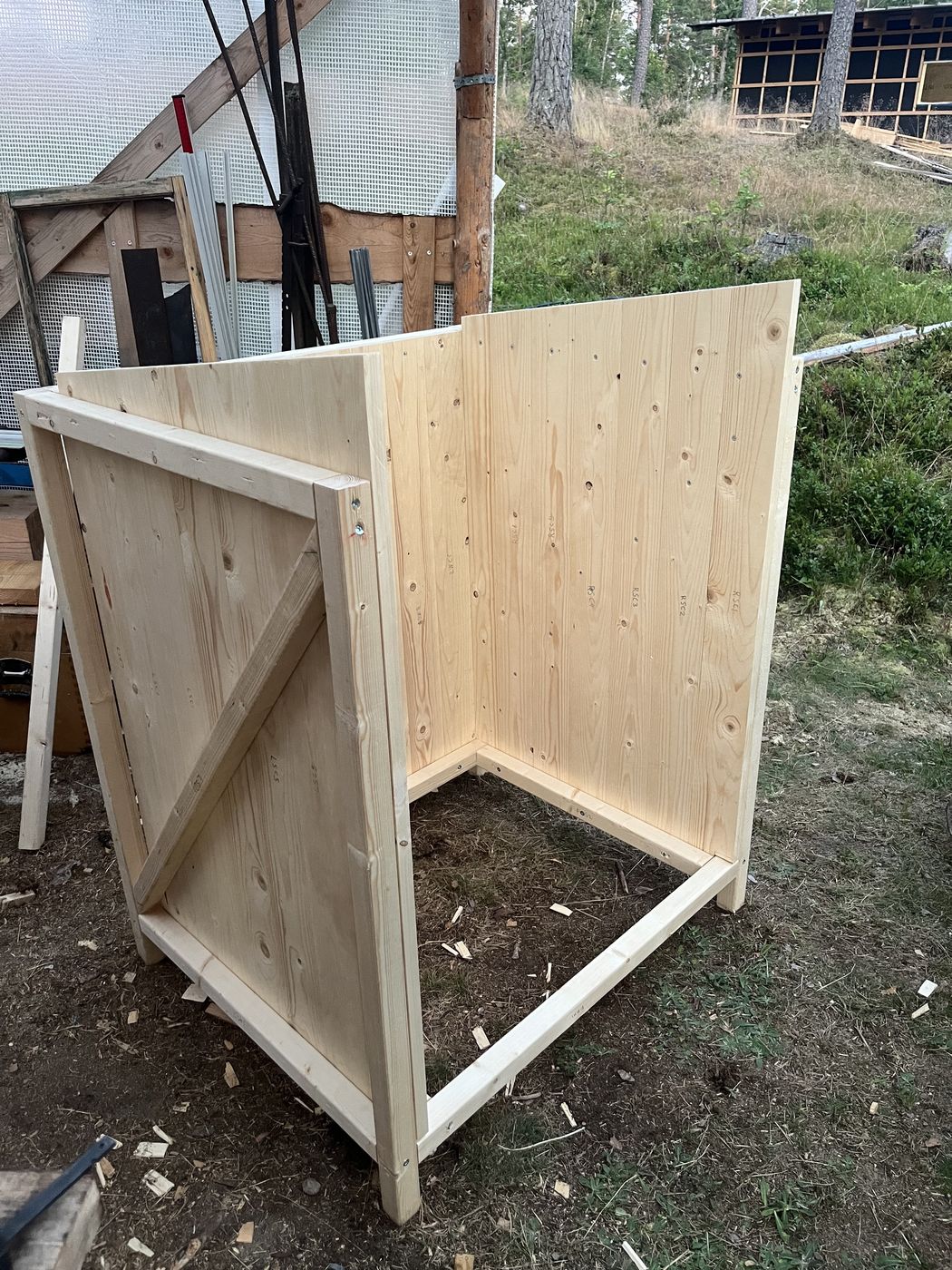
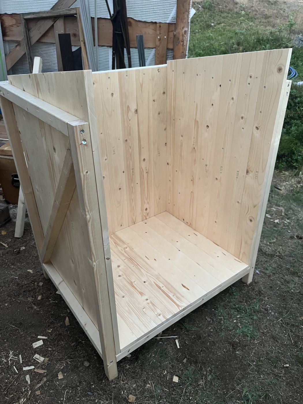
- Each unit builds through a numbered sequence of single-operation drawings, with the back panel clad and trimmed flat before it is set between the sides and the floor deck cut before it is fixed.
- Terminal-board cladding fixings are centred after trimming, and edge fixings clear the modeled beam-screw paths.
- The interactive line, textured, fallback, and print views share the in-situ render's perspective, scale, and position.
- Stack H carries all eight beam screws, and Stack J plus the final open SVG use the same model-aligned isometric projection.
- Seat-top boards run across the removable box, with outer supports and two additional frame screws, to improve integrity around the opening.
- The seat box is removable at 852 mm, with fixed shell supports, so the box remains serviceable while its front and rear edges stay supported.
- Diagonal brace ends and screw paths avoid the frame corners, so the fastening audit can report clear nominal paths.
- The model gained fastening and angle checks, so workshop assembly can be checked against the measured frame.