WORKING DRAWING

Can AI build a toilet yet?

An experiment in re-drawing a technical drawing as an editable parametric CAD model with Claude and Codex.
Project
DASS
Issue
2026-07-30
Architect
@hannes.soderquist
Code
@feelepxyz
Source
GitHub
Units
Millimetres
Kerf
2.8 mm per cut
Sheets
A-200 to A-400
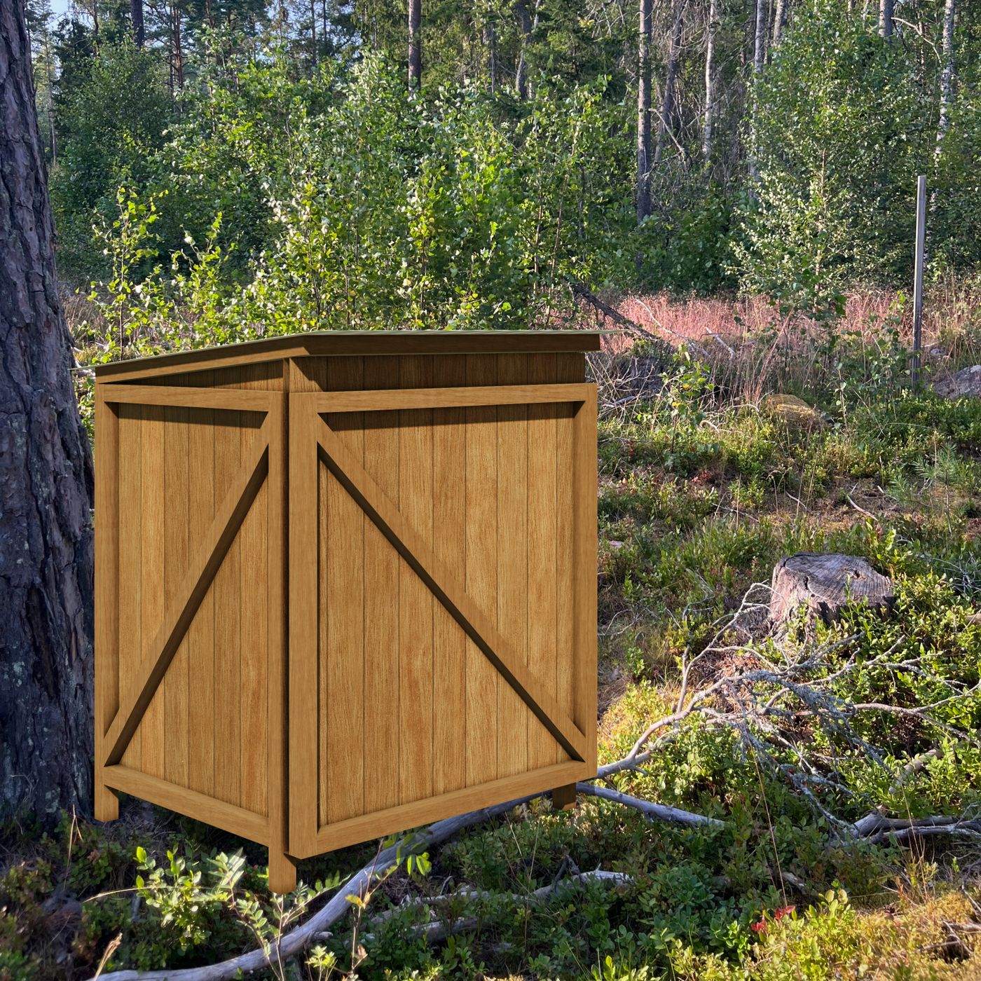
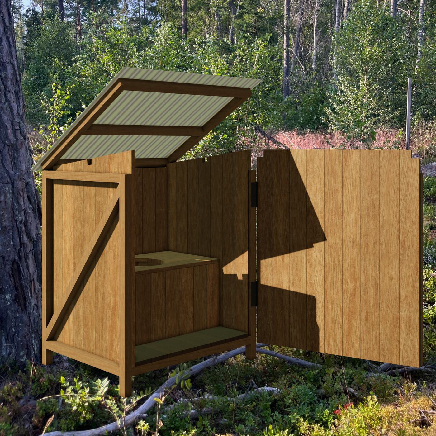
The finished building rendered in the drawing-set palette

Loading the model…

Model Finish
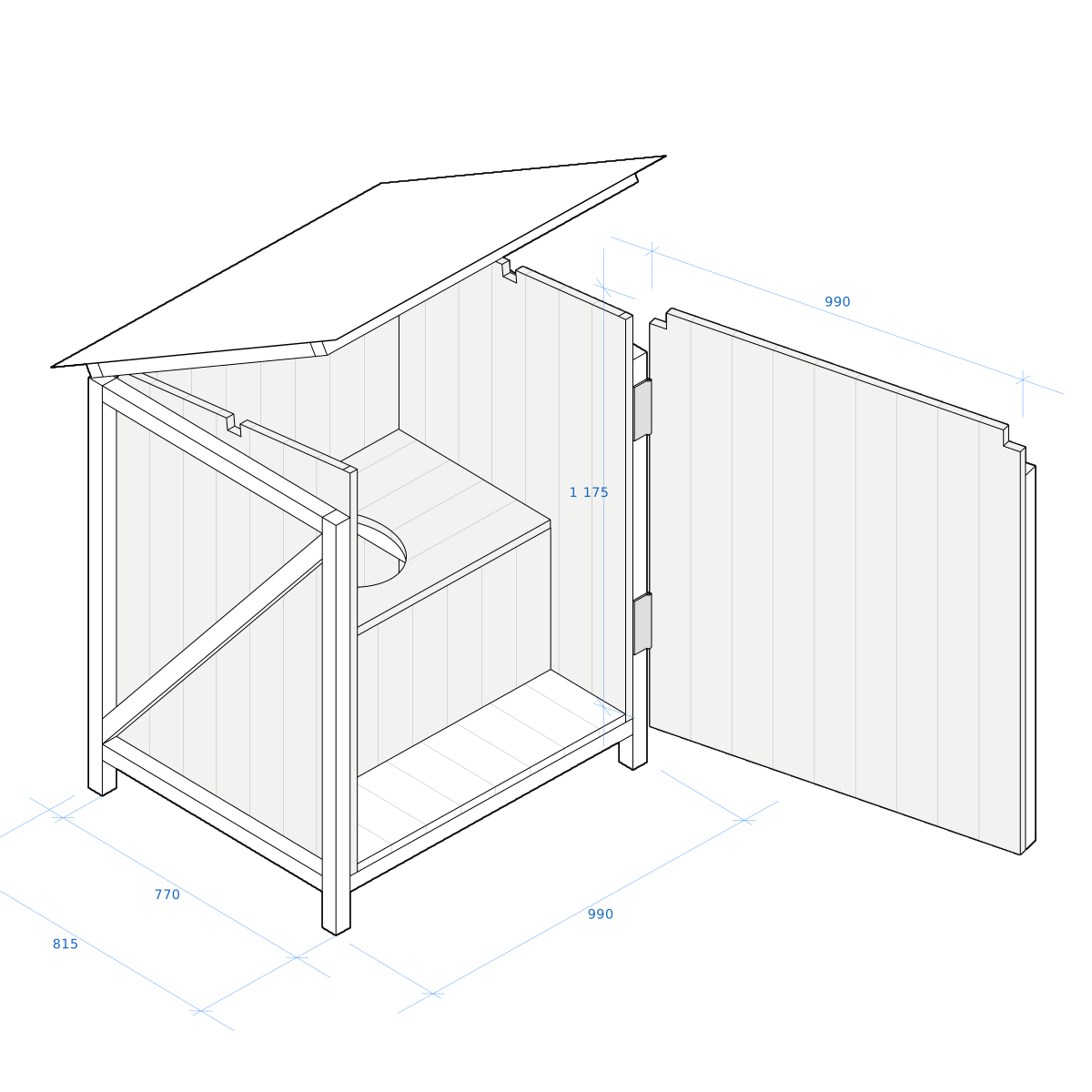
Interactive line model. Drag to rotate, scroll or pinch to zoom, and click a piece to identify it.The finished building.
Sheet A-200

Structural timber

Material

Frame timber, 45 × 45 × 4 200 mm. Quantity: 9 lengths.

The 9 beam stock lengths below are named B01 to B09. Each cut diagram shows the marked beam pieces cut from that length.

Cut every piece at one stop setting before you change the stop. A batch that reaches the end of a stock length continues on the next length.

These sheets are exact only for this material size. One 2.8 mm kerf is used for every piece.

If your material ends are rough, shave a small amount off from each piece first.

3 pieces
3 pieces
3 pieces
4 pieces
4 pieces
4 pieces
5 pieces
5 pieces
5 pieces
Sheet A-300

Råspont (matchboard/V-groove cladding)

Material

Råspont (matchboard/V-groove cladding), 120 × 23 × 4 500 mm. Quantity: 12 lengths.

The 12 cladding stock lengths below are named P01 to P12. Each cut diagram shows the marked boards cut from that length.

The first 8 stock lengths release all twenty-three 1 175 blanks. Label the P01 to P03 remainders. Keep them for the final 397 pass. Fourteen side boards come next, then nine door boards, at one stop setting.

These sheets are exact only for this material size. One 2.8 mm kerf is used for every piece.

If your material ends are rough, shave a small amount off from each piece first.

5 pieces
5 pieces
5 pieces
3 pieces
3 pieces
3 pieces
3 pieces
4 pieces
4 pieces
5 pieces
6 pieces
6 pieces

Gaps between boards change the joined width. Fix each board to its unit frame before you mark any final edge. Use the frame edge to set the circular-saw guide. Cut only after the boards are fixed. Sheet A-400 shows each estimated overhang and cut line.

Sheet A-400

Unit drawings and assembly

Each unit opens with its general arrangement, dimensioned and coded off the model, then builds through its own numbered steps. A step draws one operation: work already done ghosts back, work this step touches goes solid, and the band under the drawing names the operation before the caption is read.

Black screw paths are measured 120 mm screws: each starts on the source beam and finishes in the centre of the receiving section. Diagonal paths follow the diagonal beam from its mitred end.

Assembly hardware

Use these fasteners for the timber assembly.

UseFastener
Frame beams and braces6 × 120 mm sunk wood screws
Beam-to-beam support joints, for example floor supports6 × 90 mm sunk wood screws
Råspont (matchboard/V-groove cladding) to beams2.8 × 60 mm nails or 6 × 60 mm sunk wood screws
Stack A

Roof unit

0 / 3
  1. RBH1RBH2RBS1RBS2RBC1ASSEMBLE45 × 45 STOCK
    1Lay the five roof beamsA-401.1
  2. RBS1RBS2RBH1RBH2RBC1FASTEN6 × 120 · 6 OFF
    2Screw the frame cornersA-401.2Match the frame diagonals before you drive a screw.
  3. RBS1RBS2RBH1RBH2RBC1303091.191.1ASSEMBLE1 050 × 1 085 SHEET
    3Centre the metal sheetA-401.3
Stack B

Door unit

0 / 5
DCB1DCB2DCB3DCB4DCB5DCB6DCB7DCB8DCB9DBV1DBV2DBH1DBH2DBD122.5147.59901 0501 175
DOOR UNITA-402 · FRONT ELEVATIONseen from outside the door · hatched edge is the estimated on-frame trim
  1. DBV1DBV2DBH1DBH2DBD1ASSEMBLE45 × 45 STOCK
    1Build the frame and fit DBD1A-402.1
  2. DBV1DBV2DBH1DBH2DBD1FASTEN6 × 120 · 12 OFF
    2Screw the door frameA-402.2Match the frame diagonals before you drive a screw.
  3. DCB1DCB2DCB3DCB4DCB5DCB6DCB7DCB8DCB922.5147.5ALIGN DCB1CLAD2.8 × 60 NAILS
    3Fix DCB1 to DCB9 on the inside faceA-402.3
  4. SAW GUIDE10CUTCIRCULAR SAW
    4Trim the right overhangA-402.4
  5. 4545CUTHANDSAW
    5Cut the two top reliefsA-402.5
Stack C

Left side

0 / 7
LSC1LSC2LSC3LSC4LSC5LSC6LSC7LSV1LSV2LSH1LSH2LSD122.5147.57701 17510045 × 45 NOTCH
LEFT SIDE UNITA-403 · LEFT ELEVATIONfront edge to the right · 100 fall over 770 · 45 × 45 bottom-front notch
  1. LSV1LSV2LSH1LSH2LSD1ASSEMBLE45 × 45 STOCK
    1Build the side frameA-403.1
  2. LSV1LSV2LSH1LSH2LSD1FASTEN6 × 120 · 12 OFF
    2Screw the side frameA-403.2Match the frame diagonals before you drive a screw.
  3. LSC1LSC2LSC3LSC4LSC5LSC6LSC722.5147.5ALIGN LSC1CLAD2.8 × 60 NAILS
    3Fix LSC1 to LSC7, front to rearA-403.3
  4. 1 1751 075MARKCHALK LINE
    4Mark the slope at front and rearA-403.4
  5. CUTCIRCULAR SAW
    5One gang cut along the markA-403.5
  6. SAW GUIDE10CUTCIRCULAR SAW
    6Trim the rear overhangA-403.6
  7. 4545CUTHANDSAW
    7Cut the bottom-front notchA-403.7
Stack D

Right side

0 / 7
RSC1RSC2RSC3RSC4RSC5RSC6RSC7RSV1RSV2RSH1RSH2RSD122.5147.57701 17510045 × 45 NOTCH
RIGHT SIDE UNITA-404 · RIGHT ELEVATIONfront edge to the left · 100 fall over 770 · 45 × 45 bottom-front notch
  1. RSV1RSV2RSH1RSH2RSD1ASSEMBLE45 × 45 STOCK
    1Build the side frameA-404.1
  2. RSV1RSV2RSH1RSH2RSD1FASTEN6 × 120 · 12 OFF
    2Screw the side frameA-404.2Match the frame diagonals before you drive a screw.
  3. RSC1RSC2RSC3RSC4RSC5RSC6RSC722.5147.5ALIGN RSC1CLAD2.8 × 60 NAILS
    3Fix RSC1 to RSC7, front to rearA-404.3
  4. 1 1751 075MARKCHALK LINE
    4Mark the slope at front and rearA-404.4
  5. CUTCIRCULAR SAW
    5One gang cut along the markA-404.5
  6. SAW GUIDE10CUTCIRCULAR SAW
    6Trim the rear overhangA-404.6
  7. 4545CUTHANDSAW
    7Cut the bottom-front notchA-404.7
Stack E

Back unit

0 / 5
  1. BWH1BWH2BWD1ASSEMBLE45 × 45 STOCK
    1Build the bare back frameA-405.1Hold it square while you clad it. Nothing screws it until the posts do.
  2. BWC1BWC2BWC3BWC4BWC5BWC6BWC7BWC822.522.523ALIGN BWC1CLAD2.8 × 60 NAILS
    2Fix BWC1 to BWC8 to the landing marksA-405.2Clad and trim the back flat. Fitted first, the side skins foul this overhang.
  3. LANDING MARK36CUTCIRCULAR SAW
    3Trim the right overhangA-405.3
  4. BWH1BWH2BWD1ASSEMBLECLAMPS
    4Set it between the two side unitsA-405.4
  5. BWH1BWH2BWD1LSV2RSV2FASTEN6 × 120 · 12 OFF
    5Screw the rear posts into BWH1 and BWH2A-405.5
Stack F

Shell joint

0 / 2
  1. FBB1FBS1FBS2FBH1ASSEMBLE45 × 45 STOCK
    1Fit FBB1, FBS1, FBS2 and FBH1A-406.1
  2. FBB1FBS1FBS2FBH1LSH1RSH1BWH1100100FASTEN6 × 120 · 8 OFF
    2Screw all four beams to the shellA-406.2
Stack G

Floor deck

0 / 2
  1. FBB1FBS1FBS2FBH1SAW GUIDE36CUTCIRCULAR SAW
    1Trim the right overhangA-407.1
  2. FCB1FCB2FCB3FCB4FCB5FCB6FCB7FCB822.522.5ALIGN FCB1CLAD2.8 × 60 NAILS
    2Fix FCB1 to FCB8 to the bearersA-407.2
Stack H

Seat box

0 / 5
  1. SBH1SBH2SBS3SBS4SBS1SBS2ASSEMBLE45 × 45 STOCK
    1Build the removable seat boxA-408.1
  2. SBH1SBH2SBS1SBS2SBS3SBS4FASTEN6 × 120 · 8 OFF
    2Screw the box frameA-408.2Match the frame diagonals before you drive a screw.
  3. STB1STB2STB3STB4STB53333ALIGN STB1CLAD2.8 × 60 NAILS
    3Fix STB1 to STB5 across the topA-408.3
  4. BOX FRAME EDGE60CUTCIRCULAR SAW
    4Trim the front overhangA-408.4
  5. 270330CUTJIGSAW
    5Cut the seat openingA-408.5
Stack I

Seat box supports

0 / 3
  1. SBB1SBB2SBF1352477INSIDE BACK FACESET OUTSPIRIT LEVEL
    1Set both beam tops above the deckA-409.1
  2. SBB1SBB2SBF1FASTEN6 × 120 · 4 OFF
    2Drive one screw from each sideA-409.2
  3. SBB1SBB2ASSEMBLELIFTS OUT WHOLE
    3Lower the box onto SBB1 and SBB2A-409.3
Stack J

Seat front cladding

0 / 3
  1. SFB1SFB2SFB3SFB4SFB5SFB6SFB7SFB8ALIGN SFB1CLADLOOSE BOARDS
    1Lay SFB1 to SFB8 in orderA-410.1
  2. 85436CUTCIRCULAR SAW
    2Trim the field to the opening widthA-410.2
  3. SBF1SBB122.567.5FASTEN2.8 × 60 NAILS
    3Screw every board to SBF1 and SBB1A-410.3